


Firstly the tip:
Do plenty of saves while you work with different file names. In case you do not like the results and maxed out on your undo steps (which you can increase in the settings btw) you are able to revert back to the previous saved version.
We start by creating a box that should have the length and beam or your desired ship. Lengthwise I suggest between 5 and 7 segments (too much more will not make you happy here) , beam and height wise 3.

Picture 1
Turn your box into an editable poly. Then tick the box Use NURMS Subdivision under the Surface properties tab. Two iterations should be enough (you can go for 3 if you want the object to be smoother, but these settings can easily increase your number of Polygons, which you want to keep low). You will see how there is a mesh created between the vertices of the object.
Also tick the box Separate by: Smoothing Groups
Everything in the same smoothing group will be smoothed – makes sense doesn’t it.

Picture 2
Use the Polygon selection and select all parts of the hull but the deck, and now Clear All Smoothing groups.

Picture 3
Now your whole hull is smoothed excluding the deck. I would put the hull into group 9 now. (I usually use grps 1-8 for the deck, 9-16 for the hull and 17-24 for hull extrusions)

Picture 4
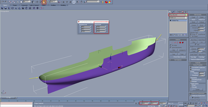
Now you can use the Vertex selection and the Non-Uniform Scale tool to adjust your hull shape from the top. Pull the central section close together, we will need it to extract the keel later.
All hull shaping might look a little odd at first but it will come together in the end!

Picture 5
Once you are happy with it, use the polygon selection again and select parts of the upper deck you want to extrude, eg. the forecastle deck, bridge or the poop deck.

Picture 6
This step may look a bit awkward at first as you can see:

Picture 7
But we will fix this by selecting the different Polygons and assigning them to the correct smoothing group. The sides selected below should get a complete new group since we do not want them to smooth with the deck, nor the hull.

Picture 8

Picture 9
Next we are going to shape our side view to the desired design. If you realized that I gave you bad advice and you need more length sections you can use the Slice Plane tool, rotate and place the plane as needed and then hit the Slice button to get more vertices in the object.

Picture 10
Give your bow and stern nice lines and move them up a bit if you like. Or simply leave them flat ig you go for a modern ship. Then adjust the stern similar to what is shown below.

Picture 11
Narrow the hull aft down a bit. (careful that you select the correct vertices, as you can see I had to x-out two wrongly selected ![]()

Picture 12
Select the keel and extrude it (I actually decided to leave the topmost part shown in this selection out of the extrusion, as you will see 4 pictures below)

Picture 13
Looks odd again...

Picture 14
... so we adjust the vertices to make that look a bit better:

Picture 15
Now we select the keel and give that a different smoothing group. If you assign two smoothing groups to a poly gmax will try to keep each of their shapes but smooth out the transition between both of them, so play around with that a bit.

Picture 16
Next we adjust the bow section. Pick the lower, outer vertices on both sides and scale them in a bit. Scaling rather than moving helps you move both sides symmetrical. Play around until you like the results.

Picture 17
If you are going for a more modern ship you can make an extrusion at this point (like we did aft) and go for a bulbous bow.

Picture 18
Pull out the top sections of the bulwark out a bit if you like.

Picture 19
Then Pick all lower, outer vertices and pull them up a bit:

Picture 20
Looks like a ship!

Picture 21
Once the hull shaping is complete, create a copy of your hull, change the color and name of your copy and position it in the same place, so the two hulls overlap exactly, THEN HIDE THE ORIGINAL! Also make a save with a different filename.
I decided to round the sections between the lower decks and the side walls, by assigning them to the same smoothing groups. (you will see why in a minute) The upper decks have different smoothing groups.
Now select all deck space of your copied hull and delete it.

Picture 22
The result should look something like this:

Picture 23
Create another copy of this deck-less hull, change the color, select ALL faces and flip the Normals. This way we create the inside of the hull.

Picture 24
Now I suggest to scale the inside down so we get a bit of “thickness” to the hull. (I suggest length 99.7% and beam 99%)
Picture 25
Create another copy of your original hull that we hid away, rename it to something “deck” and convert it into an editable poly (I know it is already an editable poly). You will see that the smooth hull that you created with a few vertices now becomes “locked” and all grid points that have been set using the iterations of the subdivision all the way in the beginning, are hard vertices that can be moved. – NEVER WORK ON YOUR HULL IN THIS STATE (it will always look sh*t :D) and remember you cannot reverse this step.

Picture 26
Select everything but your decks and delete it.

Picture 27
Your ship should now look something like this:

Picture 28
Now you can decide where you want to lower your deck below the bulwark and where you want to leave it having railing sit on top. In my example that is just going to be on the forecastle deck. With the Polygon Selection and pull it down.

Picture 29
Apologies I took this screenshot after the next step but it should give you an idea how to do it. The deck will stick out of the hull as seen below, which makes sense, so scale it down a bit to fit.

Picture 30
Next we are going to close the gap between inner and outer hull. Place a smooth line on the bow bulwark and generate the mesh around it (I suggest to only do one side and then mirror it over. So I will demonstrate it with the stbd side). If you do not know how to do that, I suggest my tutorial about line shaping, that will explain exactly what you need. Don’t pick too many iterations and sides for the mesh to save some polygons – a model of this size will probably have a lot of detail and keeping the polygons as low as possible is key for good performance of gmax and your future render.
Try a 15 to 20 thick bulk (depending how much you scaled your inner hull down you might need a bit of material here)

Picture 31
Place as many lines as you need and align them to the hull, then you can connect them for ease of handling. Klick on a line, select the Attach Mult. function and select all lines you with to attach. Then confirm.

Picture 32
Copy the Line, mirror it and position it on the port side.
Your final result should now look like this!

Picture 33
For inspirations ideas or questions have a look at Simtropolis Shipyard !


Sign In or register to comment...
To comment in reply, you must be a community member
Sign In
Already have an account? Sign in here.
Sign In NowCreate an Account
Sign up to join our friendly community. It's easy!
Register a New Account